
Technical Insights
A practical look at how PLCs, HMIs, SCADA platforms, historians, and databases work together to control industrial processes and turn plant-floor data into useful operational information.

Modern industrial facilities generate enormous amounts of information. A motor may have a running status, fault condition, current draw, speed, temperature, and operating mode. A tank may have level, pressure, temperature, valve positions, and alarm limits. A production line may track counts, cycle times, downtime, rejects, and equipment states.
Making all of that information useful requires more than a PLC and an operator screen. That is where a SCADA system comes in.
SCADA stands for Supervisory Control and Data Acquisition. At a high level, a SCADA system connects industrial control equipment with the people and systems responsible for operating, monitoring, troubleshooting, and improving a facility.
But SCADA is not a single piece of software or a single computer. A modern architecture may include field instrumentation, programmable logic controllers, industrial networks, SCADA servers, HMI clients, alarm systems, historians, relational databases, reporting tools, MES platforms, and enterprise systems.
Understanding what each layer does is the first step toward designing an industrial automation system that is reliable, maintainable, and capable of turning plant-floor information into useful operational data.
In This Article:
The Basic SCADA Architecture
A simplified industrial automation architecture can be viewed as a series of connected layers:

Information typically moves upward through this architecture while commands, setpoints, and production requirements can move downward.
At the plant floor, instruments and equipment generate signals. PLCs process those signals and execute control logic. The SCADA layer collects information from the controllers and makes it available to operators. Historians and databases preserve information for later analysis. Higher-level applications can then use that information for production reporting, downtime analysis, OEE, quality tracking, maintenance, and other business functions.
The exact architecture varies by facility, but the basic idea remains the same: each layer has a specific role, and the system works best when those roles are clearly defined.
Field Devices: Where Industrial Data Begins
Every SCADA system ultimately starts with the physical process.
Field devices include instruments and equipment such as level transmitters, pressure sensors, flow meters, temperature transmitters, proximity switches, motor starters, variable-frequency drives, control valves, actuators, and safety devices.
These devices interact directly with the process. Consider a tank with a level transmitter. The transmitter measures the actual liquid level and sends that signal into the control system. A pump may simultaneously provide running, fault, speed, and current information.
At this level, the system is dealing with physical conditions. The SCADA system does not create that information; it receives data that originates with the process and has typically been collected and processed by a controller.
PLCs: The Real-Time Control Layer
The programmable logic controller, or PLC, is responsible for controlling the process.
A PLC reads inputs from field devices, executes programmed logic, and determines what outputs should do. That could mean starting a motor, opening a valve, maintaining pressure using PID control, sequencing equipment, or stopping a process when an interlock is violated.
This distinction is important: the PLC controls the process; SCADA supervises the process.
For example, an operator might use SCADA to request that a pump start. SCADA sends the command to the PLC. The PLC then determines whether the pump is actually allowed to start. It may verify that valves are positioned correctly, permissives are satisfied, no equipment faults exist, and no safety interlocks are active.
Time-critical process control and equipment protection generally belong in the controller rather than depending on an HMI screen or SCADA server. A temporary loss of an operator workstation should not automatically mean that basic controller logic can no longer operate.
HMI: How Operators Interact With the Process
An HMI, or Human-Machine Interface, is the visual interface between a person and the control system.
The HMI may display equipment status, process values, alarms, trends, setpoints, operating modes, diagnostic information, and control buttons. It may be a local touchscreen mounted on a machine or one of many operator stations connected to a larger SCADA system.
That is why HMI and SCADA are related, but they are not necessarily the same thing. An HMI is primarily the operator interface. A SCADA system provides the broader supervisory infrastructure behind that interface, potentially including centralized tags, alarming, historical data, multiple operator stations, remote facilities, reporting, and integration with other systems.
Good HMI design is therefore about more than making a screen look attractive. Operators need to quickly understand process state, abnormal conditions, active equipment, material flow, and what requires attention.
The SCADA Server or Gateway: The Supervisory Layer
Between the PLC and operator interface is often a SCADA server, gateway, or group of servers. This layer acts as the central communication and supervisory platform.
The SCADA platform may communicate with PLCs through industrial protocols and technologies such as EtherNet/IP, OPC UA, Modbus TCP, or vendor-specific drivers. It converts controller data into tags that applications can use throughout the supervisory system.
Those tags may represent values such as silo level, conveyor status, pump discharge pressure, production count, motor current, valve position, or equipment faults.
Once those values exist at the supervisory layer, they can be displayed on HMI screens, historized, alarmed, used in calculations, written to databases, or sent to other systems.
The communications between these layers depend heavily on the facility’s industrial networking and OT architecture. Network segmentation, device communication, redundancy, addressing standards, and remote access can all affect SCADA reliability and maintainability.
Alarming: Turning Conditions Into Operator Actions
Displaying process values is only part of the job of SCADA. The system also needs to tell operators when something requires attention.
An alarm might indicate high pressure, low tank level, equipment failure, communication loss, abnormal temperature, or another condition requiring action.
Effective alarming is more than changing an object to red. A properly engineered alarm should communicate a meaningful abnormal condition, identify its priority, help the operator understand what happened, and support an appropriate response.
Alarm history can also become valuable operational data. Instead of only asking, “What is wrong right now?”, a facility can begin asking which alarms occur most frequently, which conditions normally precede shutdowns, and which equipment causes the most operator interventions.
The Historian: Recording What Happened Over Time
Real-time data tells an operator what is happening now. An industrial historian tells the facility what happened five minutes ago, yesterday, last month, or during a previous production run.
Historians are designed to capture time-series process information such as temperature, pressure, level, speed, production counts, motor current, valve positions, and equipment states over time.
That history makes trends and event reconstruction possible. For example, an operator investigating a pump trip might examine discharge pressure, motor amperage, flow, tank level, and valve position during the minutes leading up to the event.
Without history, the operator may only know that the pump is currently faulted. With history, the engineering team can reconstruct what happened. That difference is extremely valuable for troubleshooting, process optimization, reliability analysis, production reporting, and continuous improvement.
Historian vs. SQL Database
The terms historian and database sometimes create confusion because their capabilities can overlap.
A historian is primarily focused on efficiently recording values that change over time. A relational database such as Microsoft SQL Server or PostgreSQL is generally better suited for structured information and relationships between records.
Historian data might contain thousands or millions of time-stamped values for motor current, pressure, temperature, or equipment state. A SQL database might instead store production orders, batch numbers, operator actions, downtime reasons, products, recipes, work centers, shift information, or maintenance records.
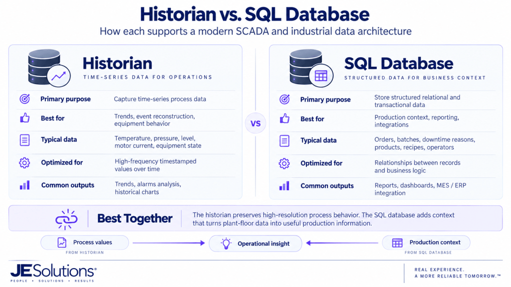
The distinction is not always physical. Some historian platforms use relational databases for storage, and a SCADA platform may use the same database server for several different functions. It is more useful to think about the purpose and structure of the data than to assume that historian data and relational data must always live on completely separate systems.
A well-designed architecture may use both. The historian preserves high-resolution process behavior, while the relational database adds production context. Together, they can answer much more valuable questions.
Turning Process Data Into Production Information
Suppose a production line stops. The PLC knows the equipment is no longer running. The SCADA system displays the stopped condition. The historian records when the equipment changed state.
But the business question usually goes further: Why did it stop?
To answer that reliably, the system may need to know what product was running, what production order was active, which fault occurred, how long the equipment was stopped, whether the downtime was planned or unplanned, and which machine caused the line to stop.
When SCADA information is combined with contextual database information, the system can begin calculating metrics such as downtime duration, cycle time, throughput, reject rate, availability, production efficiency, and Overall Equipment Effectiveness (OEE).
This is the transition from simply collecting industrial data to creating usable production information. JESolutions’ Industrial Data & Analytics work focuses on this connection between control systems, historians, SQL, MES, reporting, and operational dashboards.
A Practical SCADA Example
Consider a bulk material handling facility with storage silos, conveyors, valves, motors, and loading equipment.
Level transmitters measure how much material is inside each silo. Limit switches report valve positions. Motor starters and VFDs provide running, stopped, fault, speed, and current information. The PLC collects those signals and controls the equipment sequence.
When an operator selects a destination and requests a transfer, the PLC verifies that the required equipment is available and that the correct material path is established. The SCADA system then gives the operator a visual representation of the process.
The active material path can be highlighted. Equipment status can be displayed. Alarms can identify failures. Trends can show motor current or process conditions.
Meanwhile, the historian records important operating values and equipment states. A database can record each transfer, including the source silo, destination, product, start time, completion time, quantity, operator, and production order.
A dashboard can then use that information to calculate throughput, downtime, equipment utilization, transfer duration, recurring faults, and other performance indicators.
The same general architecture can be applied to water and wastewater facilities, pharmaceutical processes, manufacturing systems, energy facilities, food and beverage production, chemical processes, and many other industrial environments. The equipment changes, but the fundamental information flow is often similar.
SCADA Architecture Is More Than Drawing Screens
One of the most common misconceptions about SCADA development is that the work primarily involves drawing process graphics. Visualization is important, but the architecture behind those graphics is often more important.
A maintainable SCADA system requires decisions about controller interfaces, tag structures, equipment models, naming standards, alarming, historian strategy, database architecture, cybersecurity, network design, redundancy, navigation, user permissions, server architecture, deployment, and long-term support.
That is why SCADA engineering sits at the intersection of several disciplines. Controls engineering determines how the process operates. HMI engineering determines how operators interact with it. OT networking determines how systems communicate. Data engineering determines how operational information is stored and contextualized.
Those decisions affect not only the initial project but also how easily the system can be expanded, troubleshot, upgraded, and supported years later.
How Modern SCADA Systems Scale
A small facility might use one SCADA server communicating with several PLCs and a database. A larger facility may separate communication, visualization, historian, and database workloads across multiple servers.
An enterprise may operate several independent plants while sending selected production information to a centralized corporate system. Remote facilities may use local or edge gateways so control and data collection can continue even when communication to a central system is unavailable.
The correct architecture depends on factors such as process criticality, number of devices, number of clients, network topology, historical-data volume, cybersecurity requirements, redundancy requirements, geographic distribution, and future expansion.
The important question is not simply, “Which SCADA software should we buy?” It is, “What architecture does this operation require?”
From Plant-Floor Control to Operational Intelligence
A well-designed SCADA system creates a bridge between the physical process and the people responsible for operating and improving it.
The PLC provides reliable real-time control. The HMI gives operators visibility and interaction. The SCADA platform connects and supervises the system. The historian preserves process behavior over time. Databases provide production context. Analytics, MES, and reporting systems transform that information into operational insight.
When these layers are designed independently, facilities can end up with fragmented data, inconsistent interfaces, difficult troubleshooting, and systems that become increasingly difficult to maintain.
When they are designed as parts of one connected architecture, the result is much more powerful:
FIELD → CONTROL → SUPERVISORY → DATA → ENTERPRISE
That is the foundation of a modern industrial automation system.
Designing or Modernizing a SCADA System
JESolutions designs, integrates, modernizes, and commissions industrial automation systems across the control and information layers—from PLC programming and controls and HMI/SCADA development to industrial networking, historian and database integration, MES connectivity, and production data architecture.
Whether a project involves a new facility, an existing SCADA system, a platform migration, additional equipment, historian integration, or a broader industrial-data initiative, the architecture should be built around the process, operators, reliability requirements, and long-term needs of the facility.